Pegger set up
Instructions
Pegger has been developed on ArcView3.x. So, you have to have ArcView3.x installed on the machine where you plan on running Pegger.
Make sure to install the appropriate extensions as well, e.g. Spatial_Analyst or 3D_Analyst.
Before you start with Pegger, the appropriate files typically are prepped in ArcGIS such as contour layers, slope class layers, stream layers, etc, anything that impacts road locations.
From the DEM file you create
1. Contour shape file with appropriate contour interval. Typically select 1 ft contour interval. It provides for a better pegging alignment than a standard 10-ft contour map
2. Create also a 10-ft contour shape file. This layer typically will be displayed during the pegging process. The pegging actually will use the 1-ft contour layer, since it will provide for a smoother grade line.
3. Create additional layers such as slope class maps, stream map, roads, etc. It helps in visualizing where to go with the pegged routes and which areas to avoid.
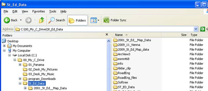
4. IMPORTANT!!: Store those folders and files in the C-directory (NOT “My documents). ArcView does NOT tolerate any empty spaces in folder and file names.
1. 
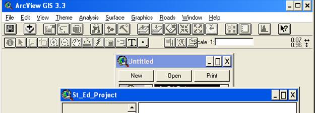
Start AcView
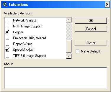
Check boxes in Extensions for , Pegger, Spatial Analyst
And any other extension that may be appropriate, if any
Make sure to have
Pegger and Spatial Analyst active
(check box under File>Extensions)
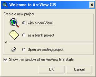
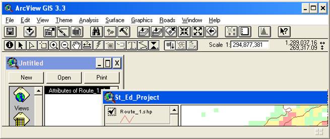
Check create new project > check “ as a blank project
Click on New > Project > Rename > type the
Project name (e.g. St_Ed_Project)
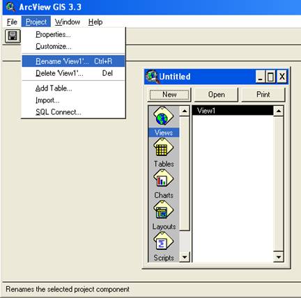
Then click “Open”
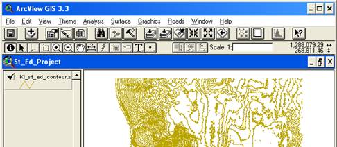
To add themes (or layers) click on +


Then navigate to the proper directory where the layers are
Select the desired layer (e.g. Kl_st_ed_contour.shp), click OK
Add both the 1 ft contour.shp and the 10 ft contour.shp layer
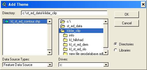
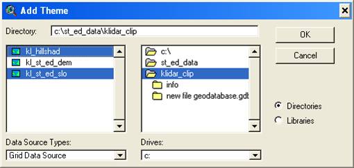
Make sure, that
“Data Source Types” drop-down-window is set to
- “Feature Data Source” for
shapefiles, e.g. contours, roads, streams, etc.
- “Grid Data Source” for Slope classes, DEM’s, etc
- “Image Data Source” for Hillshade, Orthophoto, etc.
The layer gets added but does not yet display.
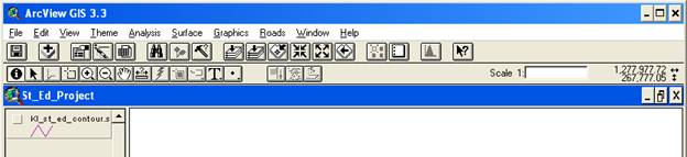
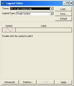
You can change the display lines, etc by double-clicking on the layer theme and select line color, etc
|
|
|
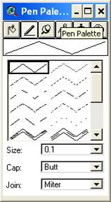
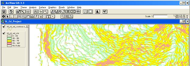
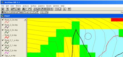
To help with the pegging
process it is useful to add additional layers such as
·
slope class, to help
with identifying critical areas
·
hillshade to help
with terrain visualization
·
stream layers
·
etc..
Again click on the “ Add Theme” button, navigate to
folder.
Slope classes and hillshade
themes are rasters, so make sure to select “Grid Data Source” in drop down
menue.
hillshade themes are “Image
Data Source” so select it in the Drop-Down menue.
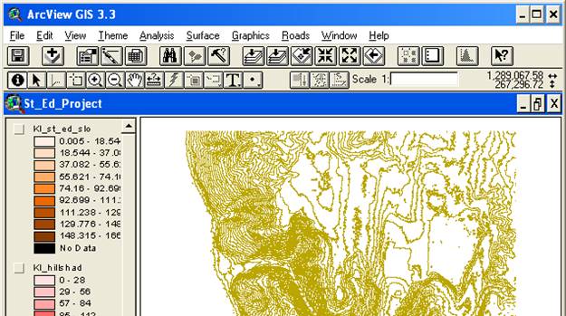
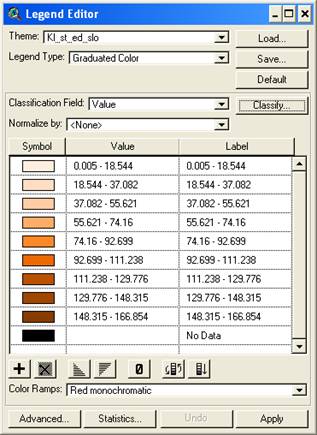
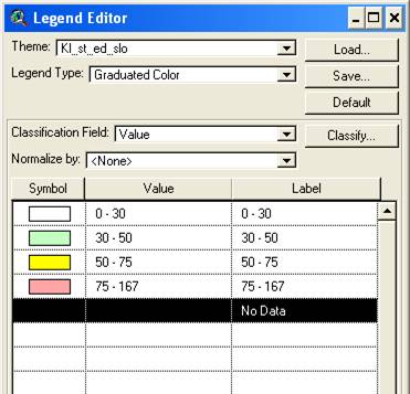
Slope class breaks have to be set now to the desired values. Double click on the slope class layer,
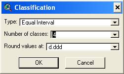
then click on “Classify”
Then select the desired colors (double click in the color box) and type in the desired slope class range and breaks - click “Apply” button
|
|
|
To delete a theme click on “ Edit” > “Delete” in the GUI
Starting the Pegging Process
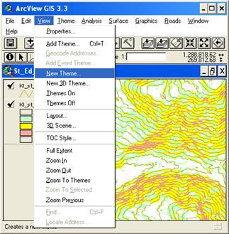
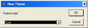
Create new road theme
View > new theme
(the one you are going to peg). Make sure to select “line”
|
|
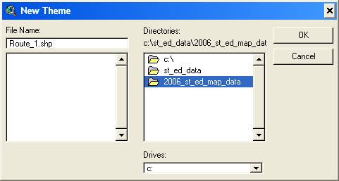
Save it to the proper location
|
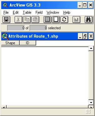
Next you have to create the correct table layout
Make the new road theme active by clicking on the layer in the Table of Content (Start Editing)
Theme > Table
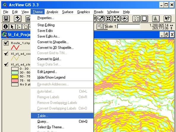
Open now the table to create the necessary fields to store grade info and road names
|
|
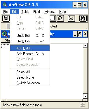
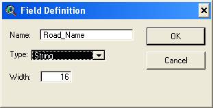
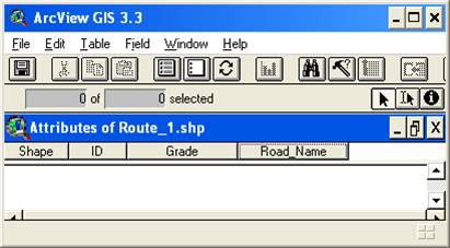
Add fields for “Grade” and “Road_Name” Edit > Add Field
|
|
Make sure to define
the Type (Number or string)
|
|
|
|
|

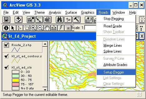
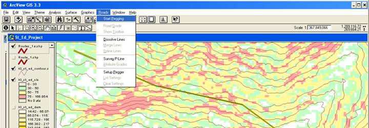
Close table view and open “Setup Pegger” to finish the setup process
Roads > Setup pegger
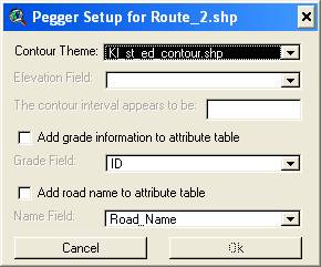
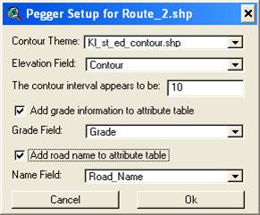
Contour theme > select the appropriate contours. Make sure to select the 1 ft contour theme
Elevation field, should show the appropriate cont our interval (e.g. 1 ft)
Grade field and road name
|
|
If Elevation Field is grayed out,
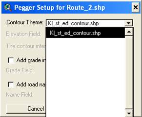
click on drop down window of Contour Theme again |
|
If elevation field does not show up, then go back to contour theme, select from drop down menu anything and try again. Usually just hung up so needs some “shaking”. pick any other field to wiggle the memory, go back and pick elevation again from selection and it should work Select the appropriate drop-down field for Elevation, Grade Field and Road Name |
|
|
|
|
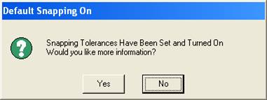
Usually click NO.
To set the
appropriate snapping tolerances
Theme > Properties, then
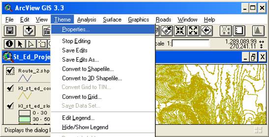
in the “Theme Properties “window click on Editing and set the desired snapping tolerances

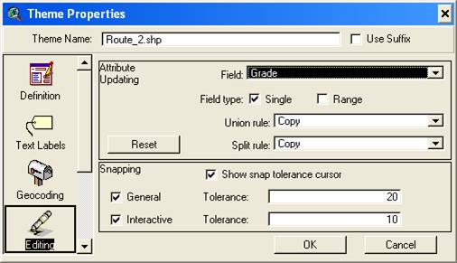
Snapping
Make theme (layer ) active (e.g. ccontour layer)
Start Editing Theme > Start Editing
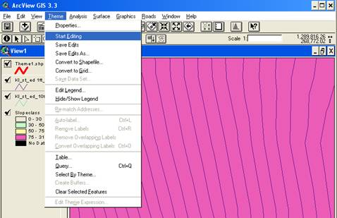
Click on snap tool (now you can set snap tolerances interactively on screen)


Click on snap tool
Then click inside map view and drag, it will set the snap tolerance distance (circle). The pegger toll will snap to the nearest vertex of a contour line within that snapping tolerance (the circle distance you just set).
Now you are ready to go
Roads > Road Grade
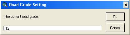
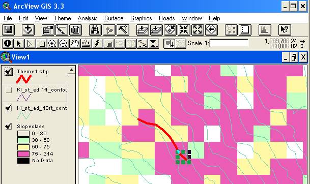
Enter desired grade and then click on the Pegger Tool
To start a new road with the Pegging tool, hold down the shift key while clicking on a contour line in the view. Pegging will begin when you click on a single contour line.

If Pegger cannot determine which contour is the desired start point then the following information will be displayed:
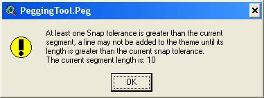
In that case, zoom in so you select just one vertex
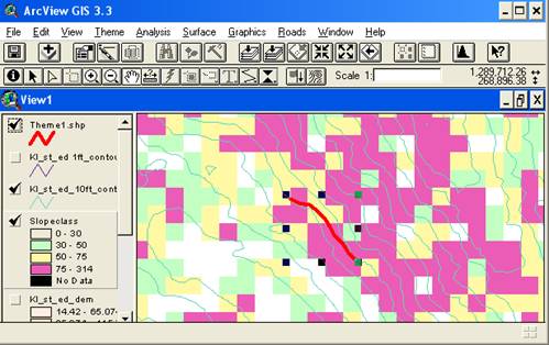
Use the “Select Tool” to select and delete unwanted pegged intervals.
To restart pegging and connect where you left off
Put Pegger Tool at the desired location you left off (e.g. last pegging interval), then
“Shift – Click “in order to connect, then move Pegger tool ahead and click as you go
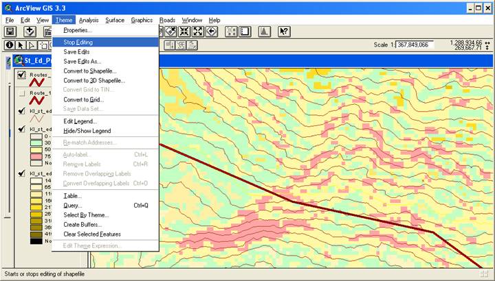
To stop editing a theme and commit your edits
Choose Stop Editing from the View's Theme menu or Stop Pegging from the Roads menu to disable editing on the theme. You will be prompted to save your edits.
Moving pegged road to
RoadEng
Pegger can export a digital road survey to RoadEng® for detailed road design. Pegger exports digital road surveys in the Criterion Unit Survey .pol format.
To survey a pegged road for export to RoadEng, either ArcView Spatial or 3D Analyst must be installed and enabled. To enable Spatial or 3D Analyst select Extensions under the File menu. In addition, a valid GRID data source or TIN data source must be in the active view and a single polyline feature selected.
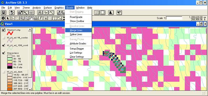
Pegger will only survey single polyline features. If you have a road made of many polyline segments, merge or dissolve the features into a single feature.
Make sure to stop editing and save the feature
To use the “ Survey P-Line” function,
1. Select the road line or segment you want exported
a. By using the “Select Feature” symbol
Survey P-Line from the Roads menu.
This will bring up a dialog where you can specify an 8-character survey name (PEGGER by default), the surface theme to use (either a GRID or TIN) and some survey options.
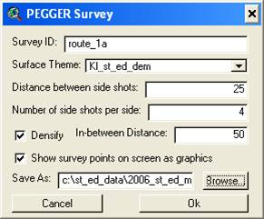
Make sure to select
surface theme, e.g. “Kl_st_ed_dem” of
the area
The Distance between side shots is the horizontal distance between side shot elevation values, perpendicular to the road or on an angle bisector if the side shots are at a Turning Point (TP).
The Number of side shots per side is the number of elevation values to collect on each side of the P-Line. If your data is stored in feet and the Distance between side shots is 25 and the number of side shots per side is 4, then 4 side shots will be taken at 25 foot intervals up to 100 feet away from the road on each side of the P-Line.
By default, Pegger only surveys the elevation surface at turning points. If you would like to survey the elevation surface at a regular interval that is more dense than the turning points then select Densify and enter a distance between survey points.
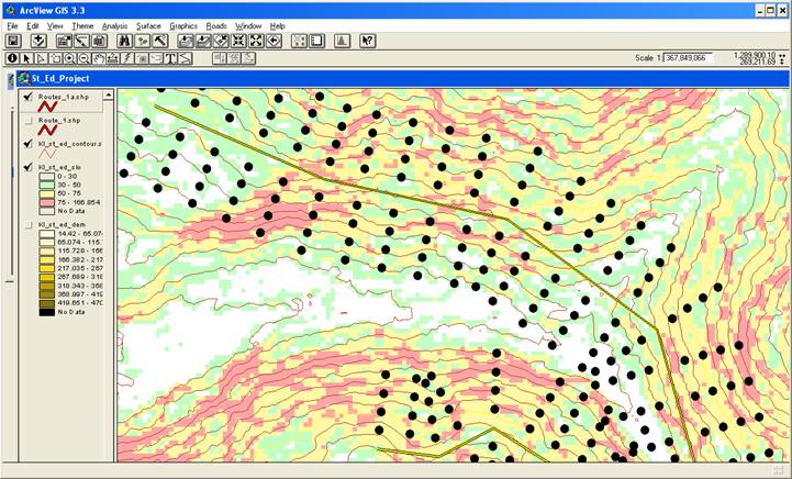
Optionally, the survey points can be drawn in the active view as graphics, This allows you to see the points where Pegger is surveying the elevation surface and preview what will be imported into RoadEng.
By default, Pegger will name the output unit survey .pol file with the same name as the shapefile being surveyed and place it in the same directory. If you would like to specify an alternate location or name, select Browse…
Information about how to import a Pegger survey into RoadEng, see the topic
Importing Unit Survey
Into RoadEng